
Hypotube Skiving & Catheter Transition Zones: Grinding vs. Laser Profiling, Kink Testing, and RFQ Sourcing
Compare hypotube skiving by grinding and laser profiling, plan catheter transition kink tests, and prepare drawing-based RFQ inputs for an engineering review.
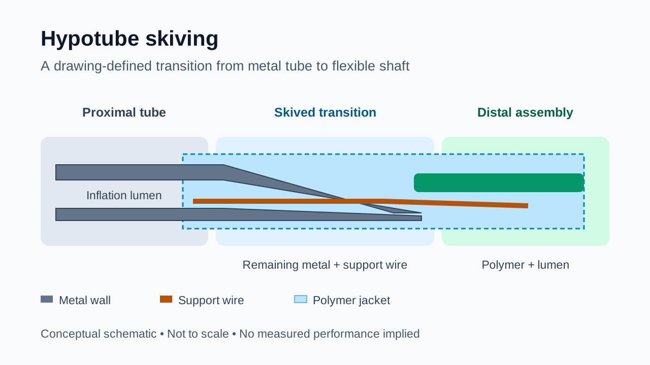
Hypotube skiving removes part of a metal tube wall to form a transition into a more flexible catheter shaft. For engineers and buyers working on balloon and rapid-exchange (Rx) catheters, the decision is not simply which process cuts the taper: it is which combination of profile, edge finish, core-wire attachment, and polymer assembly preserves lumen patency and joint integrity.
Core sourcing takeaway: Compare rotary grinding and laser profiling against the same finished drawing and inspection criteria. Grinding can suit repeatable planar bevels; laser profiling can suit contoured features and integrated slots. Neither process name guarantees burr-free edges, zero heat effects, better kink resistance, or lower total cost. Request finished samples and separate machining, finishing, inspection, and setup charges.
Published and technically reviewed: October 29, 2026. Scope: Global medical device OEM engineering, CDMO manufacturing, and component procurement. This is an editorial DFM and sourcing framework, not a report of physical testing. No supplier yield, certified process capability, clinical outcome, or standard pass limit is established here. The OEM must determine device-specific requirements and the applicable regulatory pathway.
Start with our balloon catheter application guidance, laser-cut hypotube options, and 5-axis laser cutting capability scope. For a specific design, send a drawing for feasibility review.
1. The Catheter Transition Dilemma: Resolving the Mechanical Step-Down
A proximal metal shaft helps transmit push and torque, while the distal assembly must bend through the intended path. An abrupt change in geometry or assembly stiffness can concentrate bending near the joint. Skiving redistributes metal along the transition, but the remaining ribbon can also twist, buckle, or damage a liner if poorly supported.
For a straight, homogeneous circular tube in small-deflection bending, flexural rigidity is E × I, with I = π × (Do⁴ − Di⁴) / 64. Here E is elastic modulus and Do and Di are outer and inner diameters. This expression describes the intact tube section. A partial skive has a different neutral axis and direction-dependent section properties; a bonded metal/polymer/core-wire assembly needs a composite model or measured response.
Design implication: Compare bending in the skive plane and across it. Reducing metal alone does not establish a smooth stiffness gradient or adequate hoop support. Include the actual liner, jacket, bond overlap, and guidewire configuration in assembly evaluation.
2. Skive Geometry Architectures: Profile Comparison
- Straight linear bevel: A planar cut leaves a progressively smaller metal section. Define the angle or profile coordinates, heel blend, toe cutoff, and the datum used to measure them. Inspect for a curled or sharp toe.
- Parabolic or multi-radius contour: A shaped profile provides another way to distribute the remaining metal. It does not automatically create constant bending stress; response depends on local section properties, loading, and the surrounding assembly.
- Scalloped or saddle profile: A pocket can accommodate a guidewire lumen or bond feature in an Rx architecture. Check fit, bond access, and local support without assuming the same profile suits every catheter.
- Slotted transition plus skive: Slots can soften the intact tube before the taper. Slot pitch, ligaments, slot ends, and jacket support affect bending and fatigue. Compare the hybrid with a simpler skive under the same test conditions before accepting added complexity.
3. Manufacturing Matrix: Rotary Grinding vs. Laser Profiling
This matrix is a supplier-screening framework, not measured process capability. Ultrashort-pulse and longer-pulse laser routes require different parameter development. Ask which machine, pulse regime, finishing sequence, and inspection method the supplier will actually use.
| Decision input | Rotary abrasive grinding | Laser profiling | Evidence to request |
|---|---|---|---|
| Profile and access | Often practical for planar tapers and accessible contours | Can combine contours and slots where beam access permits | Finished profile overlay against drawing datums |
| Thin remaining toe | Contact force can distort a thin unsupported section | Avoids wheel contact; thermal and redeposition effects still need review | Toe thickness, edge radius, and distortion images |
| ID edge condition | Rolled burrs or embedded abrasive may require finishing | Dross, recast, or redeposition may require finishing | ID inspection with stated resolution and defect limits |
| Heat effects | Coolant and wheel condition affect local heating | Pulse regime, fluence, scan strategy, and gas affect heat input | Agreed metallurgical checks where relevant |
| Surface finish | Wheel condition and feed leave a process-specific texture | Ablation or melt removal leaves a process-specific texture | Roughness method, location, and post-finish measurements |
| Fixtures and setup | Workholding and wheel dressing may add setup cost | Workholding, programming, and trials may add setup cost | Itemized NRE and drawing-change charges |
| Prototype schedule | Depends on stock, fixtures, finishing, and queue | Depends on stock, programming, trials, finishing, and queue | Written milestones and assumptions |
| Production economics | Compare qualified yield, cycle time, and maintenance | Compare qualified yield, cycle time, and maintenance | Quote at the same quantity, release criteria, and scope |
EDM or chemical machining may be alternatives for selected geometries, but require a separate feasibility review for access, recast or undercut, cleaning, and dimensional control. Do not treat them as interchangeable with grinding or laser profiling.
Purchasing decision rule: If a supplier cannot show the finished ID edge and toe condition, retain that as an unresolved qualification item even when the quoted unit price is attractive. Request an inspection evidence plan before comparing sample approval dates.
4. Mechanical Layout: Rapid Exchange Catheter Transition Architecture
The schematic shows one possible hybrid architecture with a skive, relief slots, a support wire, and polymer encapsulation. It is not to scale, a universal catheter layout, a manufacturing drawing, or proof of tested performance. Dimensions and attachment details must come from the approved assembly design.
Figure: Conceptual transition layout. The liner, support wire, jacket, and local metal section must be evaluated together; the illustration does not establish acceptance dimensions.
5. Kink Mechanics: Local Collapse vs. Flexural Rigidity
Thin tubes can ovalize during bending, while an axially loaded shaft can buckle. A skive changes the section from a closed tube to a partial wall, so an intact-tube collapse model should not be carried into the transition without checking its assumptions. Polymer creep, liner support, bond length, and the orientation of the remaining metal can alter the result.
Use an intact-tube control and candidate transitions with the same base tube and assembly stack. Change one design factor at a time where practical. Record bend orientation and the location of first ovalization, flow restriction, permanent set, or bond damage. Lower bending force alone is insufficient if lumen patency or joint strength deteriorates.
6. Internal Burrs, Feather Edges & Liner Integrity
Edge defects can damage a liner during assembly or bending. A cut liner may cause leakage or friction depending on the lumen architecture; a visual edge inspection alone cannot establish finished-device integrity.
- Inward burrs: Define the allowable protrusion and inspect the ID with sufficient access and resolution. "No visible burr" needs a stated inspection method.
- Feather edges: Define a finished toe thickness or edge radius and a cutoff profile. A theoretical zero-thickness edge is difficult to manufacture and inspect consistently.
- Recast or loose material: Establish finishing, cleaning, and cleanliness acceptance criteria for the selected process.
- Finishing stock loss: Measure representative parts before and after finishing. State whether drawing dimensions apply before or after electropolishing; do not assume a universal removal allowance.
A useful drawing note identifies the defect limit, inspection location, magnification or resolution, and sampling plan. Agree any destructive sectioning separately from non-destructive lot inspection.
7. Secondary Joint Processing & Evidence Handoff
The skive is only one part of the assembly. Review each secondary operation with the supplier:
- Support-wire attachment: Define material, overlap, joint location, attachment method, and loading direction. Establish pull and fatigue requirements from device risk and assembly testing, rather than a generic weld count or force.
- Cleaning and surface treatment: Select alloy-compatible processes and verify residues, corrosion behavior, and dimensions. Passivation does not remove cracks or establish biocompatibility by itself.
- Coating boundaries: Identify coated and bare regions, masking datums, and adhesion requirements at the bond interface.
- Polymer reflow or bonding: Qualify temperature, time, pressure, and internal support against the selected polymer and liner. Check lumen shape, leakage, and bond integrity after processing.
Ask the supplier to identify which operation owns each critical dimension and defect risk. A component inspection report and a finished-assembly verification report answer different questions.
8. Mechanical Qualification: Standard Scope & Test Planning
ISO 10555-1:2023 covers general requirements for sterile, single-use intravascular catheters. Its public catalogue entry establishes scope; it does not provide the complete test clauses or acceptance limits. Use the controlled standard and applicable device-specific parts to establish the protocol.
ASTM F2606-08(2021) addresses three-point bending of balloon-expandable stents and stent systems. It is not a general catheter-transition qualification standard. An adapted shaft test needs its own justification and cannot establish trackability from bending flexibility alone.
The FDA PTCA special controls guidance is US guidance for certain PTCA catheters, not universal approval criteria for PTA, neurovascular devices, or every market. It discusses device performance testing and documented protocols, specimens, acceptance criteria, and results.
The following is an editorial planning checklist, not a quotation of mandatory test methods or limits:
| Engineering question | Proposed evaluation | Record before comparing suppliers |
|---|---|---|
| Does the transition restrict the lumen during bending? | Controlled plate-gap or mandrel screening with a defined patency endpoint | Fixture geometry, bend plane, medium, temperature, pressure, guidewire state, and flow endpoint |
| Does support deteriorate during a held bend? | Dwell and recovery study under the intended conditions | Dwell time, conditioning, permanent set, and post-dwell patency |
| Is flexibility distributed as intended? | Local bending characterization at defined shaft positions | Span, contact geometry, orientation, loading rate, and force–deflection curves |
| Does the joint separate under pull? | Assembly tensile test with justified grips and gauge length | Conditioning, extension rate, failure location, force, and acceptance rationale |
| Does the processed assembly leak? | Pressure and leak testing of the relevant fluid path | Medium, pressure history, fixtures, assembly state, and leak endpoint |
| Does the assembly tolerate the intended loading history? | Risk-based repeated bending or simulated-use evaluation | Path, cycles, bend directions, sterilization/aging state, and post-test inspection |
Plate gap is not bend radius. Record the measured gap and observed shape. Converting a gap directly into radius assumes a particular geometry and can misrepresent a catheter with nonuniform curvature. Likewise, any claimed "kink threshold" must identify whether it means visible collapse, flow loss, guidewire friction, or permanent deformation.
For a homogeneous, constant-section, simply supported beam in small elastic deflection, EI = F × L³ / (48 × δ). A short, nonuniform composite transition may not satisfy those assumptions. Report the fixture and measured curve; do not present an apparent EI as intrinsic material stiffness or proof of clinical tracking performance.
Sample-release handoff: Agree specimen configuration, conditioning, endpoints, acceptance rationale, and sample-size rationale before manufacture. Request raw measurements and failure images, not just a pass certificate. Keep destructive qualification samples separate from saleable parts. A component result does not release the finished device.
9. Failure Modes, Root Causes & Prevention Matrix
These are investigation hypotheses. Confirm the cause on the actual assembly before changing the drawing.
| Observed failure | Possible contributors | Supplier investigation / prevention |
|---|---|---|
| Kink at the skive heel | Abrupt local section change, insufficient support, or bend orientation | Compare profile and jacket support; evaluate a heel blend under the same fixture conditions |
| Punctured jacket | Sharp toe, protruding burr, or assembly misalignment | Inspect finished toe and ID; review assembly tooling and support |
| Increased guidewire friction | Burrs, liner damage, local ovalization, or bonding distortion | Inspect the lumen before and after reflow and bending |
| Joint separation | Attachment defects, insufficient overlap, or bond-process variation | Identify failure location; qualify joint dimensions and attachment parameters |
| Fatigue fracture | Local notches, surface defects, or cyclic strain concentration | Review surface condition and failure origin; compare repeated-bend results |
| Inflation-path leakage | Liner or wall damage, seal defects, or assembly-process variation | Localize the leak; inspect the affected cross-section and processing history |
10. Engineering & Procurement RFQ Specification Checklist
Use the same revision-controlled requirement set for both process quotes. Values must come from your design; this checklist supplies no default release limits.
- 1. Base tube: Alloy and material condition; OD, ID, wall, length, straightness, datums, and tolerances.
- 2. Profile: Bevel, contoured, saddle, or hybrid; dimensioned drawing and CAD coordinates where needed.
- 3. Active length: Start and end datums, transition length, and tolerance.
- 4. Finished toe: Remaining thickness, cutoff or radius, edge condition, and measurement location.
- 5. Heel and slots: Blend geometry, ligament dimensions, slot ends, orientation, and relationship to the assembly.
- 6. Burr and cleanliness limits: ID/OD defect limits, loose-particle criteria, inspection access, resolution, and sampling.
- 7. Finish: Roughness location and method, finishing sequence, and whether dimensions apply after finishing.
- 8. Coating and bonding: Mask boundaries, liner/jacket materials, overlap, and assembly constraints.
- 9. Joint evidence: Core-wire details, attachment process, agreed mechanical tests, endpoints, and acceptance rationale.
- 10. Commercial and quality scope: Prototype/pilot/annual quantities, destination, required date, material records, lot traceability, dimensional report, sample approval, NRE, and change-control terms. Verify any required supplier QMS certificate and its scope separately; ISO 13485 is not a component performance certificate.
Comparable-quote handoff: Ask each supplier to return the same four items: drawing exceptions, proposed process and finishing sequence, sample inspection/test evidence, and an itemized quote with delivery assumptions. Resolve an unsupported ID inspection or assembly-test requirement before treating a lower price as a qualified alternative.
11. Frequently Asked Questions (FAQ)
When is grinding preferable to laser skiving?
Grinding is a candidate for repeatable planar profiles when workholding, wheel condition, finishing, and ID inspection are controlled. Laser profiling is a candidate for complex contours or integrated slots. Compare finished quality, qualified yield, setup costs, and volume-specific quotes; there is no universal annual-volume crossover.
How can we reduce PTFE liner damage at the transition?
Control inward burrs and toe geometry, then check liner support and the reflow or bonding process. Inspect before and after assembly. A nominal toe dimension alone does not establish protection against cutting or pinching.
What skive length should a coronary balloon catheter use?
There is no universal length based on French size alone. Select candidate lengths with the actual tube, liner, jacket, core wire, overlap, and intended bend path. Compare patency, bending response, joint strength, and simulated use before fixing the drawing.
Does electropolishing change the skive dimensions?
Yes. It removes material and can round edges, with removal depending on geometry and process conditions. Measure the actual finished part and specify final dimensions; do not copy a generic stock-loss allowance into the drawing.
Can Nitinol hypotubes be skived?
Candidate machining routes need an alloy- and geometry-specific feasibility review. Ask how heat input, surface integrity, finishing, and any required transformation-temperature or mechanical checks will be controlled. A laser pulse label alone cannot establish preserved alloy properties.
What lead time should procurement expect?
Request a dated quotation tied to stock availability, tooling/programming, trials, finishing, inspection, and sample approval. Separate first-article delivery from qualified production release. This article provides no fixed prototype or production lead-time promise.
Engineering Support & RFQ Sourcing
For a catheter transition review, start with balloon catheter application requirements and laser-cut hypotube feature options. Use the 5-axis laser cutting scope and micro-tube inspection guidance to define the questions you need answered.
Send your drawing and RFQ requirements to Medical Hypotubes with alloy, tube OD/ID, profile and length, liner/jacket constraints, quantity, and required inspection evidence. Request feasibility feedback, drawing exceptions, and a quotation for the stated scope before setting sample acceptance or delivery commitments.
Sources & References
Reviewed October 29, 2026. These primary sources establish scope and context, not guaranteed component performance, pricing, certification, or regulatory acceptance.
- ISO: ISO 10555-1:2023 — General requirements for sterile, single-use intravascular catheters. Public catalogue scope only; use the controlled full text for test clauses and limits.
- ASTM International: ASTM F2606-08(2021) — Three-point bending of balloon-expandable vascular stents and stent systems. Scope and limitations inform the distinction between stent-system characterization and an adapted shaft test.
- US FDA: Certain PTCA Catheters — Class II Special Controls Guidance. Issued September 8, 2010; applies to the devices described in its scope and provides performance-test reporting context.
Limitations and maintenance: This article does not reproduce paid standards, establish EN 13868 conformity, or provide first-hand laboratory data. The process comparison, failure hypotheses, and RFQ handoff are editorial engineering guidance requiring supplier and OEM verification. Confirm applicable editions, regulatory recognition, device-specific requirements, and supplier evidence when defining acceptance criteria. Review this guide when the drawing, assembly, process, or applicable requirements change.
Author

Categories
More Posts
Navigating FDA QMSR and EU MDR Compliance in Medical Hypotube Sourcing: A 2026 Guide
2026 guide to FDA QMSR and EU MDR impacts on medical hypotube sourcing, supplier audits, material traceability, and compliance evidence.
How to Specify Medical Hypotube Tolerances to Reduce Cost and Lead Times
Medical hypotube tolerances guide for RFQ teams: set OD, ID, wall, concentricity, straightness, and finish limits before you request a supplier DFM review.
Endoscope Snake Bone Tubing: Monolithic Laser-Cut Bending Sections vs. Riveted Vertebrae
Compare endoscope snake bone tubing designs, material trade-offs, fatigue validation and RFQ inputs. Prepare a drawing-based DFM review with Medical Hypotubes.