
1. Wire interference
Assume 23RW geometry and a 0.0140 in wire. ID = 0.0250 − 2 × 0.0060 = 0.0130 in. Clearance is −0.0010 in.
Next step: Change the lumen or wire; do not proceed with this nominal combination.
Calculate nominal ID and wire clearance, then compare wall tradeoffs and the tolerances to request. Preliminary engineering screening only.
Published , reviewed by Medical Hypotubes.
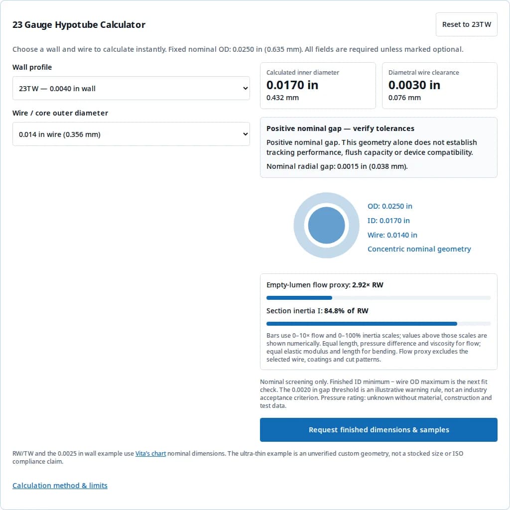
Request a drawing review & samplesChoose a wall and wire to calculate instantly. Fixed nominal OD: 0.0250 in (0.635 mm). All fields are required unless marked optional.
Calculated inner diameter
0.0170 in
0.432 mm
Diametral wire clearance
0.0030 in
0.076 mm
Positive nominal gap — verify tolerances
Positive nominal gap. This geometry alone does not establish tracking performance, flush capacity or device compatibility.
Nominal radial gap: 0.0015 in (0.038 mm).
Empty-lumen flow proxy: 2.92× RW
Section inertia I: 84.8% of RW
Bars use 0–10× flow and 0–100% inertia scales; values above those scales are shown numerically. Equal length, pressure difference and viscosity for flow; equal elastic modulus and length for bending. Flow proxy excludes the selected wire, coatings and cut patterns.
Nominal screening only. Finished ID minimum − wire OD maximum is the next fit check. The 0.0020 in gap threshold is an illustrative warning rule, not an industry acceptance criterion. Pressure rating: unknown without material, construction and test data.
Request finished dimensions & samplesRW/TW and the 0.0025 in wall example use Vita’s chart nominal dimensions. The ultra-thin example is an unverified custom geometry, not a stocked size or ISO compliance claim.
Calculation method & limits| Finding | Decision | Basis |
|---|---|---|
| Gauge alone is incomplete | Specify finished OD and ID limits instead of ordering by gauge alone. | Manufacturer dimension chart |
| 23RW example excludes a 0.014 in wire | 0.0130 − 0.0140 = −0.0010 in; choose a larger lumen or smaller wire. | Geometry used by the calculator |
| 23TW example gives a positive nominal gap | 0.0170 − 0.0140 = 0.0030 in; next check the tolerance stack. | Nominal subtraction; see worked example below |
| A larger lumen trades section inertia for flow potential | Compare empty-lumen flow and bending proxies separately. | Reproducible equations |
| A flexible assembly needs its own validation | Do not treat a tubing standard or nominal fit as device approval. | ISO 9626 scope |
RW, TW and the extra-thin example below follow the nominal 23RW, 23TW and 23XX geometry in Vita Needle’s chart. Its wall values are reference dimensions. The 0.0018 in example is a custom assumption. Labels do not establish ISO wall classification or stock availability from this supplier.
| Profile example | Wall (in) | ID (in / mm) | Empty flow ratio | Section I ratio |
|---|---|---|---|---|
| RW | 0.0060 | 0.0130 / 0.330 | 1.00× | 100.0% |
| TW | 0.0040 | 0.0170 / 0.432 | 2.92× | 84.8% |
| 23XX / extra-thin | 0.0025 | 0.0200 / 0.508 | 5.60× | 63.7% |
| Custom ultra-thin | 0.0018 | 0.0214 / 0.544 | 7.34× | 50.0% |
Cross-sections share a common scale. The figures show the metal area removed to enlarge the lumen; they do not predict kinking or fatigue life.
This page fixes OD at 0.0250 in for a reproducible comparison. Hamilton’s syringe selection guide lists a 23-gauge OD range of 0.0250–0.0255 in and ID range of 0.0125–0.0140 in for its needle family. Those values describe that catalog, not a universal tolerance or this calculator’s TW preset.
A supplier’s stock code, a needle gauge and an engineering drawing are different levels of specification. Resolve discrepancies by requesting the finished dimensions, applicable standard edition and inspection method on the quoted drawing.
Results update synchronously in your browser; there is no network calculation or waiting step. Decimal inputs are validated before any result is displayed. The permitted wall range is a tool constraint, not a manufacturing limit.
| Output | Equation | Valid interpretation |
|---|---|---|
| Inner diameter | ID = OD − 2t | Concentric, uniform, circular tube at nominal dimensions. |
| Diametral clearance | C = ID − wire OD; radial gap = C / 2 | Positive is geometric space only; zero is not a usable running fit. |
| Lumen area | A = pi × ID² / 4 | Empty lumen area; excludes a wire or liner. |
| Empty-lumen flow proxy | Q / Q_RW = (ID / 0.0130)⁴ | Hagen–Poiseuille model: equal length, viscosity and pressure difference; steady laminar flow in a straight circular lumen. |
| Section inertia | I = pi × (OD⁴ − ID⁴) / 64 | Bending rigidity is E × I. Comparing I assumes the same elastic modulus and length; it is not yield strength or kink resistance. |
| Known from this tool | Unknown here | Required next input |
|---|---|---|
| Nominal ID and gap | Worst-case finished fit | ID minimum, wire OD maximum, coating limits and ovality. |
| Empty-lumen flow ratio | Actual mL/min or flush around a wire | Fluid properties, length, pressure, occupied-lumen geometry and test data. |
| Section inertia ratio | Kink radius, fatigue life and pushability | Material condition, cut pattern, support, loading and assembly tests. |
| Gauge geometry | Burst pressure, biocompatibility and clinical suitability | Application-specific evidence and device validation. |
Use C_min = minimum finished tube ID − maximum finished wire OD. If coatings are specified separately, subtract twice the maximum inward coating thickness from ID and add twice the maximum wire coating thickness to wire OD. Do not apply a coating allowance twice when it is already included in finished limits.
| Input / output | Nominal | Worst-case assumption |
|---|---|---|
| Tube ID | 0.0170 | 0.0165 minimum finished ID |
| Wire OD | 0.0140 | 0.0145 maximum finished OD |
| Diametral gap | 0.0030 | 0.0020 = 0.0165 − 0.0145 |
| Radial gap | 0.0015 | 0.0010; bending and eccentricity remain unmodeled |
A positive worst-case gap can still bind in a bent, burred or oval tube. Agree a functional sample test, the mating wire and the inspection length; do not equate the illustrative threshold with approval.
For a hypothetical 0.0004 in radial outer coating, the 0.0250 in bare tube becomes 0.0258 in finished OD. If the receiving lumen has a verified 0.0260 in minimum ID, only 0.0002 in diametral gap remains. Those inputs are assumptions for arithmetic, not a recommended fit.
French size is an OD scale: 0.635 mm × 3 = 1.905 Fr. A 2 Fr catheter label does not establish its inner diameter. Sheath sizing conventions and product construction also vary; obtain the actual minimum receiving lumen and device compatibility information.
Assume 23RW geometry and a 0.0140 in wire. ID = 0.0250 − 2 × 0.0060 = 0.0130 in. Clearance is −0.0010 in.
Next step: Change the lumen or wire; do not proceed with this nominal combination.
Assume 23TW geometry and a 0.0140 in wire. Nominal gap is 0.0030 in. The worked tolerance assumptions above reduce it to 0.0020 in.
Next step: Request finished limits and samples. The arithmetic has not established tracking or flush performance.
Assume 0.0025 in wall, no wire and the same fluid, length and pressure difference as RW. ID = 0.0200 in. Flow proxy is 5.60× RW; section I is 63.7% of RW.
Next step: Evaluate actual flow and structural behavior. Do not select a thinner wall from the flow ratio alone.
These are calculated examples, not customer case studies, measured device performance or clinical recommendations.
| Risk / tradeoff | Why it changes the decision | Mitigation / alternative |
|---|---|---|
| Nominal fit mistaken for functional fit | Coatings, bends, burrs and ovality can consume the geometric gap. | Set finished limits and test the mating pair; consider a larger lumen or smaller wire. |
| Unnecessary tolerance tightening | A requirement unsupported by a tolerance budget can add inspection effort and supplier constraints. | Quantify the required fit first. Ask for stock geometry and custom options with separate quotes. |
| Thin wall selected only for flow | A higher ID⁴ proxy accompanies a lower annular section I at fixed OD. | Compare structural samples, length and support; consider a larger OD if the profile budget permits. |
| Cut shaft treated as an intact tube | Slots, joints and jackets change load paths and fluid sealing. | Validate the final assembly; compare uncut tubing or a supported flexible construction. |
| Coating / material capability assumed | Gauge does not establish coating thickness, surface finish, alloy condition or suitability. | Put the required condition and evidence on the drawing; request feasibility confirmation. |
ISO 9626:2016 addresses rigid stainless steel needle tubing; its public scope excludes flexible tubing and notes that incorporation in a device can require additional performance testing. The ISO catalog checked on 2026-10-29 lists the 2016 edition as published, with a revision in development. Confirm the edition required by your project.
ISO 10555-1:2023 addresses sterile, single-use intravascular catheters. Refer to the licensed standard and a device-specific verification plan for applicable requirements. Neither public abstract establishes a pressure rating, surface roughness target or compliance of the example geometries on this page.
| Drawing field | What to supply | What to confirm |
|---|---|---|
| Geometry | Finished OD/ID limits, length, straightness, ovality and end condition. | Measurement method, sampling and usable inspection length. |
| Material & processing | Alloy, temper, traceability, cut pattern and joining requirements. | Feasibility and material/process documentation. |
| Surface & coating | Inside/outside finish, coating location and finished thickness limits. | Whether dimensional limits include all treatments. |
| Mating component | Maximum finished wire/core OD or minimum receiving-lumen ID. | Worst-case fit budget and functional sample protocol. |
| Commercial & acceptance | Drawing revision, sample/production quantities and required evidence. | Quoted price, lead time, inspection plan and qualification responsibilities. |
Published 2026-10-29; sources checked 2026-10-29. Catalog examples establish only the listed supplier geometry. All flow, inertia, clearance and coating examples here are analytical calculations or explicitly stated assumptions. Availability, pricing, clinical outcomes and process capability have not been verified.
Use this page to prepare an engineering question or RFQ. Release decisions require approved drawings, material/process evidence and testing of the intended assembly. No pressure, clinical or regulatory acceptance is inferred from a calculator result.
Answers use the nominal models and source boundaries described above.
This tool uses 0.0250 in (0.635 mm) nominal OD. Manufacturer catalogs use their own dimension ranges; a gauge label does not define the complete purchase specification.
No. At the same 0.0250 in OD, the example 0.0060 in wall gives 0.0130 in ID and the 0.0040 in wall gives 0.0170 in ID. Specify OD and finished ID separately.
Do not assume they are. The 0.0025 in wall example corresponds to Vita’s 23XX nominal geometry. The calculator label is descriptive, not a cross-manufacturer or ISO wall-class equivalence.
No. Its 0.0018 in wall is a custom geometry for comparison only. Availability, tolerance, surface finish and mechanical performance require supplier confirmation.
The nominal example has 0.0130 in ID, giving −0.0010 in diametral clearance. It has interference with a 0.0140 in wire; select a different lumen or wire.
No. First check minimum finished ID minus maximum finished wire OD, including coatings. Then evaluate ovality, bends, entrances, friction and the assembled device.
It is an illustrative screening rule on this page. A positive gap below that value is marked small. It is not a standard, safety factor or acceptance criterion.
No. It is an empty-lumen ID-to-the-fourth-power ratio at equal length, viscosity and pressure difference. An occupied or noncircular lumen requires a different flow model and measurement.
Unknown from gauge alone. Alloy, temper, defects, wall distribution, cuts, joints and the finished assembly matter. Request a documented pressure test appropriate to the application.
No. 0.635 mm × 3 = 1.905 Fr is an outside-diameter conversion. It does not give the receiving catheter’s minimum usable lumen. Compare actual finished dimensions.
Its stated scope covers rigid stainless steel needle tubing and excludes flexible tubing. Device-specific mechanical validation is still necessary for a cut or assembled shaft.
Send finished OD/ID limits, length, alloy/temper, coatings, end condition, intended mating component, inspection criteria and quantity. Ask the supplier to confirm feasibility, price and lead time for that drawing revision.
Inquiry Email
Best for drawings, tolerance tables, inspection needs, and quote history.
Instant Chat
WhatsApp Engineering Support
Fast path for OD/ID, material, sample quantity, and lead-time questions.